
Description
While I've been working on myoelectric prosthetics and custom drones I've found myself wanting custom PCB's manufactured. While breadboards are great for prototyping there comes a point where you need the smaller size that PCB's provide for testing. Trying to fly a microdrone with a breadboard strapped to it provides little use in testing when a PCB will weigh significantly less. I've known about a desktop PCB mill called The Ant for a while but becuase it is nearly impossible to find 1010 T-Slot in the UK I've avoided making one. Instead I decided to redesign The Ant to accommodate 2020 T-Slot which is easily sourced in the UK. The initial design is finished and I've successfully produced one using a 3D printer and some stupidly expensive and difficult to find stepper motors.
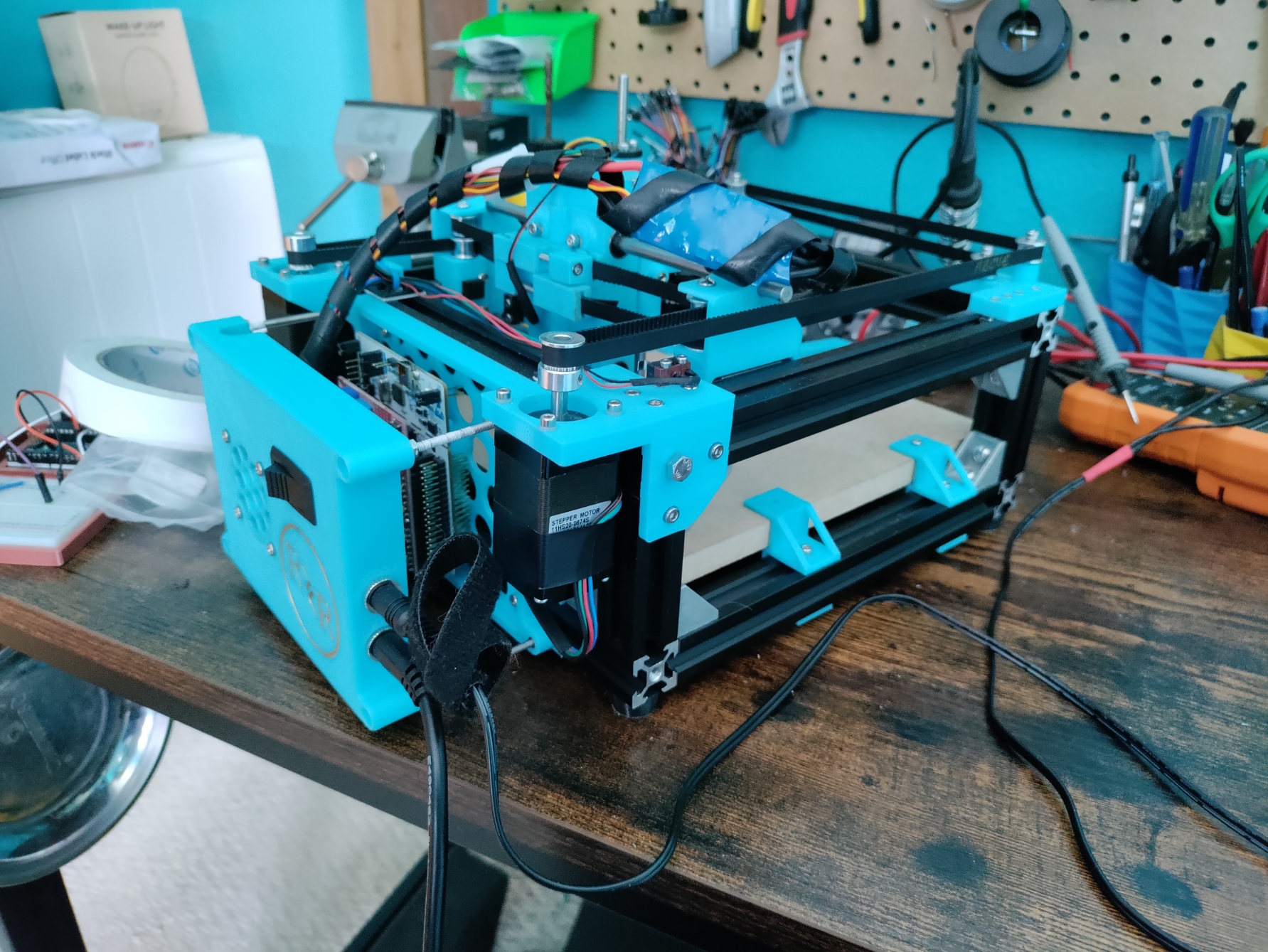
The mill uses a CoreXY layout consisting of 2 NEMA11 steppers working in unison to move in the X and Y axis, the tool head moves via a NEMA8 + leadscrew in the z axis. The spindle is a CR6 shaft with an ER8 collet on the end and turns using a drone motor connected using o-ring's as a "belt". The mill is controlled using a modified version of GRBL for use with drone ESC's installed on a nucleo board.
The real question though is does it work or have I just made an overcomplicated pen plotter. So far I've dabbled in milling and engraving aluminium and PCB's. Looking at the aluminium cuts first:
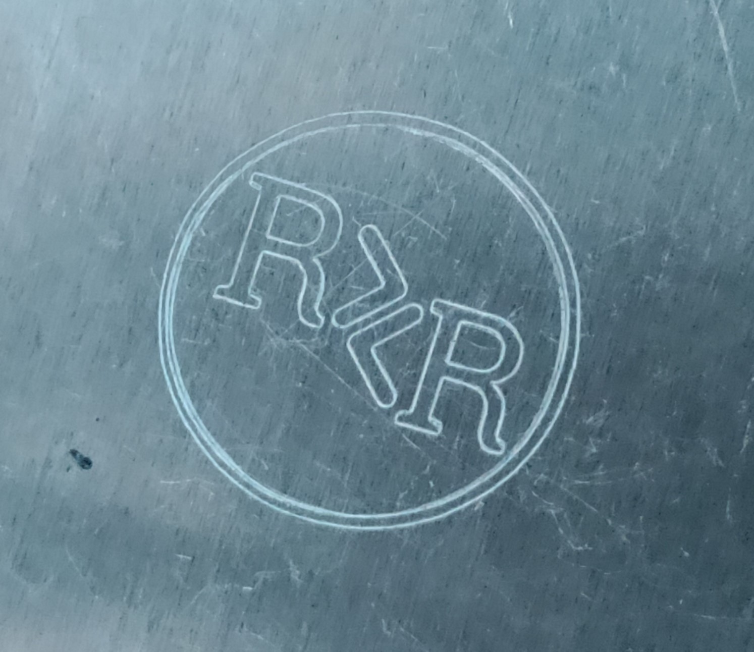
My logo engraved in Al was the first cut I ever ran, feedrate was fairly low at ~120mm/min and could definately be turned up as high as 300mm/min with the proper feeds and speeds, this is an area I'm learning as I go as I've done very little machining before this. My next attempt was to make some cuts using a cutting bit and as you can see this didn't work very well and I'll discuss why later.
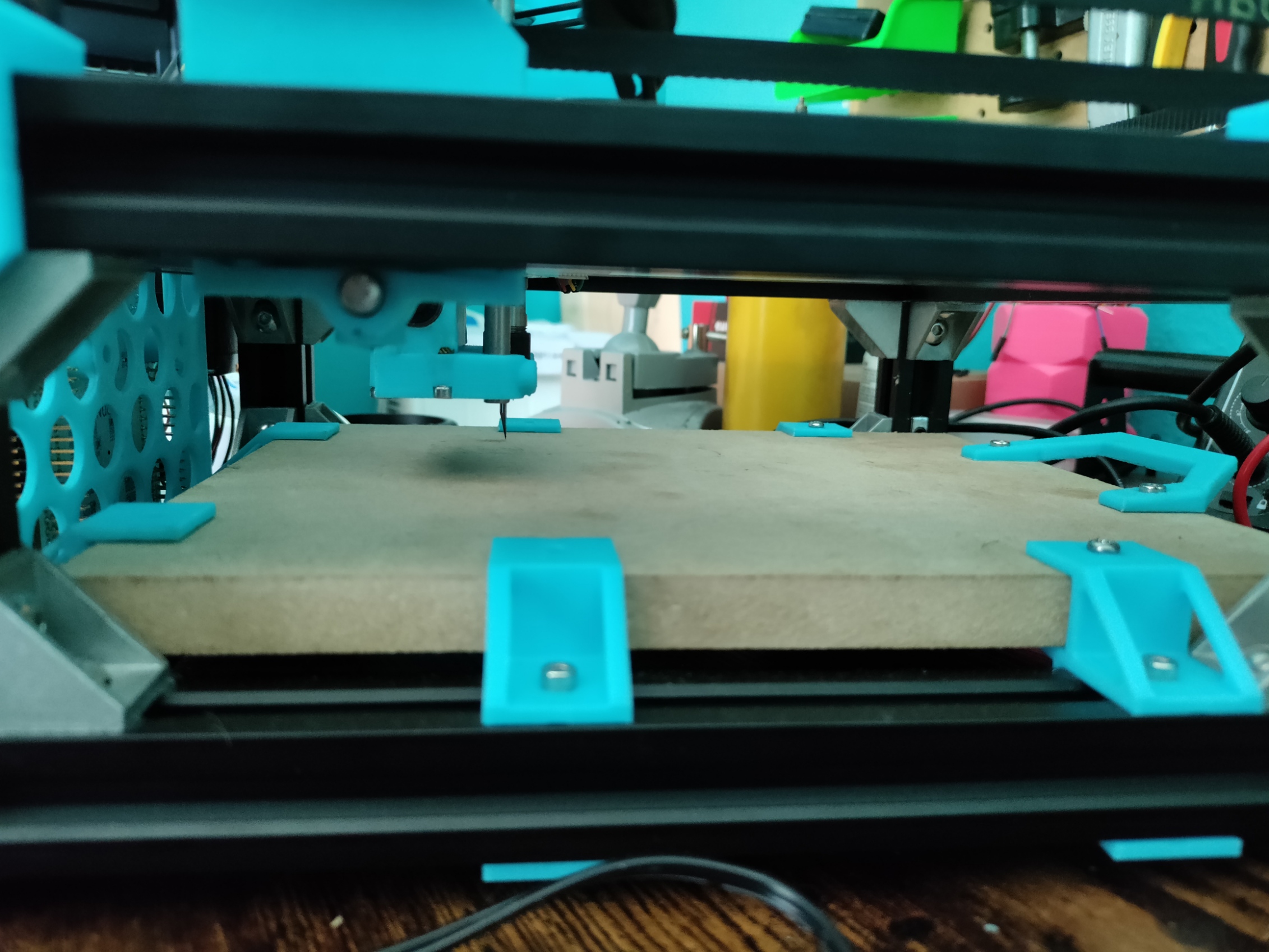
Moving onto cutting PCB's, this is where this machine shines, probably because this was the main purpose of the original:
The circuit board I'm using as a test was designed by me and will be used as a spindle controller for this machine, more on that later as well. Again, I'm still learning feeds and speeds, flatcam and how many passes are needed for good seperation of traces. The machine cuts through copper clad very easily and I've found engraving at around 250mm/min at around what should be around 8000rpm is good.
The Problems and Improvements Needed
The machine is far from perfect however. The biggest issue and the one most preventing me from using this machine more is the motor collet. The thing will not stay on the motor shaft at high RPM's. The initial design involved a spindle pulley inside of a locking coller held onto the motor shaft using a grub nut.
This failed quite catastrophically spontaneously and fired the locking collar across the room... I still have yet to find it. The next iteration, I designed the collar to be pressed inside of the pulley, this means no plastic touches the shaft and should prevent failure.
So far that hasn't been the case, at high RPM's the wieght difference between the collar and the pulley has caused the pulley to come loose and fly off while the collar stays on the shaft. My solution has been to use an actual bolt as apposed to a grub nut and a dab of glue on the mating surfaces, the shaft of the bolt locks the pulley and collar together and this coupled with the addition of glue should prevent the pulley from coming loose and embedding in me. I've also since installed a shroud around the motor pulley to prevent said embedding. This should allow me to run the machine at higher RPM's as previously I've avoided running the machine at higher speeds due to not wanting to be hit in the face with a projectile previously spinning at 8000rpm.
The other issue I have with the machine is the way the firmware controls the RPM. Due to the toolhead using a drone motor as a spindle, speed control is done via a drone ESC. Standard DC motors commonly use PWM to control speed and this is the method of speed control GRBL natively supports. ESC's use a system similar to how servos are controlled and therefore the designers of The Ant have adapted a fork of GRBL for using with an ESC. This isn't implemented extrenemly well. For a start the spindle motor used is rated at 1000kV meaning it will spin at 1000RPM per volt supplied. Theoretically this means the spindle at 12V will run at 12000RPM but is probably slightly running in anger. However, in gcode the maximu RPM is set to 1000 so running a command like M3 S500 to which normally would set the RPM to 500 is actually setting the spindle to ~6000RPM. This is where the spindle controller I've been using as a test project comes in. The plan is to use stock GRBL with RPM controlled via PWM using the spindle controller board as a middle man to convert the PWM signal to the signal understood by the ESC. This also allows me to have a manual overide for the RPM implemented to adjust RPM on the fly. There are other more minor issues with the machine, but as I'm already planning on designing a slightly larger more rubust version that can cut Al properly I'll fix those in the new design. For now the machine works and it cuts PCB's to a level good enough for what I need and as an initial design I would classify it as a success.