
Description
I've always wanted to get into custom drone making. When I first bought a 3D printer, one of the first things I made was a drone chassis for the small all in one drone circuit boards you can buy on eBay. That was about 3 years ago, but recently I was harvesting some components from a dead DualShock 2 controller and it occurred to me that I could use the analog sticks for a drone controller. I figured if I was going to make the drone controller from scratch I might as well go the whole hog and design the drone from scratch as well.
Section 0 - The Plan
First off the actual drone, I'll need a chassis, but that's probably the easy bit. I can design one of those fairly easily, it may have the aerodynamics of a VW T25 but as long as it does the job till I get a functional prototype it doesn't really matter. I'll also need drone motors and a battery to power the thing. This will be a standard 3.7V LiPo battery. I'll be controlling the thing by an Arduino most likely run off 5V through a boost convertor. The drone will also need some form of a sensor so it can balance itself, the MPU6050 I have hanging around will probably do the job, if not I'll use a triple-axis magnetometer. Last but not least on the drone I'll need an RF transceiver to communicate with the controller. I might get away with just a receiver but I have a feeling I'll probably need to transmit and receive signals from the drone.
As for the controller, I have the analog sticks I stole off an old controller which I can use for inputs along side a couple of buttons. I'll use an Arduino for processing everything and another transceiver for sending and receiving signals. I might run the controller off AA batteries or steal a phone battery off one of the dead phones I have lying about. So that's the plan. Now all I need is to wait for everything to arrive from China.
Note: The write up of the work in sections 1 - <Insert Number> was performed in one session but the work spanned over ~2 months
Section 1 - Motors
The design in my head is not for a large drone, mainly because the bed on my printer is only 200mmx200mm and the design in my head is for a unibody chassis. I believe the type of drone I'm imagining is called a micro-quad or micro-drone. Anyway, because of this the motor's I need need not be particularly large. Initially, I picked some 615 motors, but after going through several iterations of propellers and chassis' I switched over to 8520 motors (8.5mm⌀x 20mm). The 8520's are larger so they run cooler, have more torque and are just a better motor than the 615's. Also, they had £2 off on Amazon. The 8520's run at about 15000kv or 15000RPM per volt. Most likely I'll be running them at 3.7V so the RPM will be 55500, though this may be slightly less when the load of the propellers is added to the motors.
Section 2 - Chassis
Since writing Section 0 I've gone through 3 iterations of the motor. The first of which had the aerodynamics of a of Williams 2019 F1 car:
Chassis Mk1 took about 5 minutes to design and existed mainly to test different propeller designs while being able to keep my hands away from the props, though I ditched it when I changed motor sizes. There isn't much to say about this chassis other than it was poorly designed, weighed too much and it now sits on my window ledge questioning its existence. The main issue with it was the thickness of the arms. They were way too thick causing about 20% of the thust generated by the props to be distributed onto itself pushing the drone down.
Mk2 was a redesign of Mk1, made to fit the new larger motors. It was designed as a slightly lighter version of the Mk1. I have no images of this version as I never fabricated a physical version, nor do I have the CAD files as shortly after designing this model I scrapped it for Mk3.
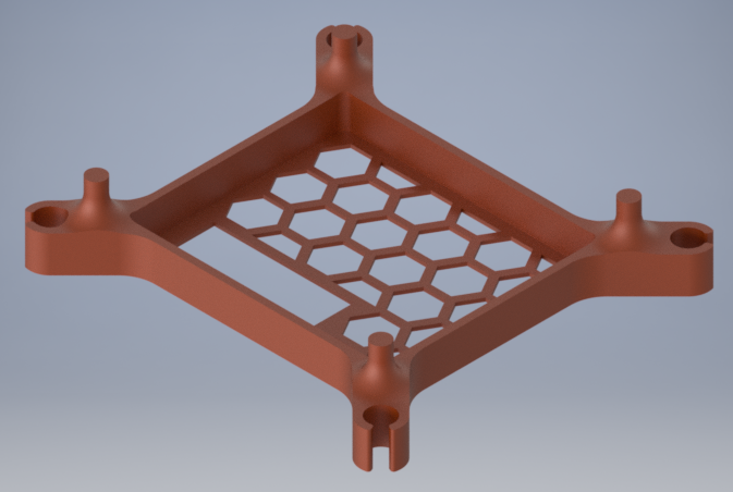
For Mk3 I scrapped the bulky unibody design for a more compact design. This design was under half the weight of the Mk1 and was designed as 2 different parts: the body and the arms. To drop some weight I ditched the hexagon mesh floor and cut 3 holes in each side of the body. These holes not only cut some weight off the chassis but also allowed for a place to route the cables coming from the motor through to the body. I added 4 small tabs on the inside of the walls, this allowed for me to screw the Arduino Nano to the body.
IMAGE Mk3
The arms of the Mk3 were designed to connect to the body via a hinge. This allowed for the arms to fold up when the drone was not in use, but ultimately this is a useless feature of the design and I ended up glueing the hinge in place. The arms also had holes cut into them to drop some weight. They were also made thinner in the middle to remove some of the surface area which would be hit by the thrust of the props. The Mk3 is currently the most recent version of the chassis I have designed, however I'm now planning a Mk4 in my head to rectify some problems I have with the Mk3. First off, I want to change the micro-controller I'm using from an Arduino Nano to either an ATTiny or Atmega32U4 Beetle Board to lose more weight. I also want to fix the arms to the body to make it a unibody design again, and finally I want to add some feet back to the design as I just purely forgot to add some to the Mk3.
Section 3 - Propellers
Getting a good propeller design has been one of the larger time consumers. 5 iterations later, I now have a design that supplies good thrust. The initial version was a propeller I found online and modified slightly to fit the 0.8mm shafts of the motors that were fitted to the Mk1 chassis I was using at the time. These were mainly a test to see if the printer I own actual had the resolution to be able to print something as delicate as a propeller so I wasn't wasting my time designing a prop that I would never be able to fabricate. Fortunately they printed fine:
IMAGE Mk1
Mk2 was the first prop designed by me. This was a very basic 3 blade prop, the fins were slightly larger at the tip than at the root with a static pitch along the entire blade. While these did create a thrust, they certainly didn't create enough to lift anything. The blades also had a tendency of detaching from the boss at high RMP's.
IMAGE Mk2
Mk3 started to show some promise. A 4 blade prop with a higher pitch at the root than at the tip but with a consistant blade width. The lower pitch at the tip allows for the blade to cut through the air easier at the higher speed that the tip travels at compared to the root of the blade. This created more thrust but not enough to lift the motor by itself let alone attached to a chassis.
IMAGE Mk3
I could have probably left the design process at Mk4 if I'm honest. The prop supplied enoug force to lift a corner of the Mk3 chassis by itself and 4 would have been plenty. Like the Mk3 the Mk4 had a variable pitch along the blade but this time with a variable width as well. I went back to a 3 blade prop so I could make the blades wider than I could should there be 4 of them.
IMAGE Mk4
Mk5 is the newest and best variant I have designed so far. Much like the Mk4 the prop has 3 blades with a variable pitch and width. However the pitch of the blade is now curved. This allows for more thrust. The pitch of the blade at the root is ~35° and gradually transitions to ~20° about 10mm out from the boss. The curve in the blade also coincidentally allows for the blades to be much more rigid when printed. The other change made was to thicken the leading edge. This was also done in the Mk3 but is implimented much better in this version. All in all this is most likely the final propeller design as while it is undoubtedly not perfect it provides enough thrust to allow the drone to function at this time.
IMAGE Mk5